


 CDN NEWS |
  US NEWS








One of the most challenging problems to solve in a cased producing wellbore is when the casing collapses or becomes distorted and out-of-round.
Depending on severity and position of the distortion in the wellbore, casing deformation can render a wellbore worthless. So long as the well can still yield enough oil or gas to remain commercially viable, a repair is the first choice. When the well requires abandonment, it may be necessary to access the wellbore below the distortion to complete proper decommissioning.
For minor distortions, the casing roller has been in the toolbox of fishing tool companies for decades. If there is enough room for the bottom roller to get started, the rollers above are concentric and of increasing diameter. Rotation with string weight begins. The tool will only pass through when the interval is returned to drift ID.
For severely collapsed casing, returning it to normal ID typically uses the same basic principle as cable tool drilling. Insert a tapered swage in the distorted interval and pound down using the weight of the work string it until it passes through.
Unless the collapse is at significant depth, the string weight alone of production tubing will not generate enough force to push the casing back to normal. A typical bottom hole assembly would include the swage, a mechanical spang jar, and a few drill collars above the jar. This creates the ability for the string to pick up velocity before the jar closes, thus hammering the swage through the out-of-round section.
This basic process, although effective, hasn’t been materially advanced in decades.
As the illustration and link below reveals, engineering calculations can be performed to determine how much downward force is required to return various sizes, weights and grades of casing to normal ID under varying wellbore conditions.
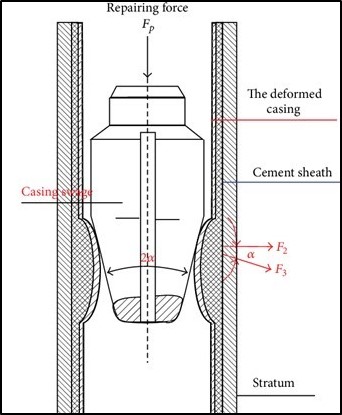
Image from: https://www.semanticscholar.org
This process only works in vertical wells, and isn’t that effective at shallow depths because of low string weight. The higher the angle, the more difficult it becomes to transfer the string weight to the swage. In horizontals, this method is impossible.
Unfortunately, horizontal wells are becoming sources of collapsed or distorted casing. This is caused by the massive pressures used in hydraulic fracturing during completions.
A helpful paper on this subject was published in the Journal of Petroleum of Technology in January of 2020. It was titled, “An Unconventional Challenge: Can Casing Failures During Hydraulic Fracturing Be Stopped?”
https://jpt.spe.org/unconventional-challenge-can-casing-failures-during-hydraulic-fracturing-be-stopped
The article contained exaggerated simulated images of what casing distortions of different types could look like. The causes include:
- Weak or low-grade casing and couplings
- Poor or unsupportive cement behind the casing
- Leaking fracture plugs that allow for severe sand erosion of the casing
- The drilling of highly undulated or contorted wellbores which create nonlinear casing loads
- High pressures involved in hydraulic fracturing
- Effects of contrasting fracturing fluid and reservoir temperatures
- The response of rock layers, bedding planes, and faults to being fractured and fluidized (i.e., tectonic reactivation or slippage)
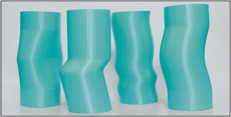
3D-printed casing segments to illustrate localized casing deformation modes: (from left) collapse, shear, helical buckling, and lateral buckle. Source: C-FER Technologies.
Completions techniques for horizontal wells continue to evolve and improve in every area. With the ability to reciprocate and rotate production casing during cement displacement, primary cement jobs have never been better.
But after displacement is completed, there is still a period of time for gravity to work its magic before the slurry sets. This makes it impossible to have the same cement density on the high side of the hole as the bottom in a horizontal well.
Winterhawk Casing Expansion Technology provides a solution for this type of casing repair. The CET has been proven to have sufficient power to deform casing and expand it beyond manufactured ID, even against cement.
If the CET will expand cemented casing, it has sufficient power to return deformed casing back to circularity and drift ID. A distorted interval will not have solid and uniform cement behind it.
Winterhawk was approached by a well operator with a unique casing deformation challenge. There was a section of casing that had been corroded by salt resulting in a modest ID reduction. The plan was to run a casing patch through the interval, but it wouldn’t fit.
A mechanical swage repair would have likely made the physical condition of the corroded interval worse.
The solution was to reduce the diameter of the CET expansion elements such that when at full power and stroke the casing would only return to drift ID. The three-element configuration of the CET was selected in order to cover a larger area with each expansion. Using a sample of the casing to be repaired, the elements were shaved so they unable to materially exceed drift ID at peak expansion. The casing to repaired was 139.7mm 23.07 kg/m with a drift ID of 122.56mm.
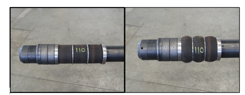
It was found that elements at 110mm OD would expand to an average of 136mm. Including the resistance against the casing, it was determined that in wellbore conditions this would return the collapsed interval to drift ID without damaging it further.
To be able to assess and repair in one trip, a drift OD gauge ring was installed on top of the CET. This became the largest diameter component of the BHA. Prior measurements confirmed that the CET and everything below the gauge ring would pass through the collapsed interval.
Once the distorted area is tagged, the tool is picked up and positioned accordingly with the elements across the area to be repaired. Depending on the length and severity of the distorted interval, multiple expansions would be required.
With the CET in the released position, sliding downhole to testing the repaired section with the gauge ring to measure progress is fast and simple.
Using samples of the casing requiring repair, element diameters and CET configurations can be surface tested prior to the job to ensure the desired outcome prior to deployment.

Expansion and ductility shop test of simultaneous three-element expansion of 177.8mm 34.2 kg/m L80 casing. The OD was increased from 3.5% to 4.8%. These expansions were conducted at about 75% of full power.
Winterhawk’s casing expansion technology has multiple applications in cased hole wellbore repair and remediation.
For more information go to: www.winterhawkwellabandonment.ca
Share This:






















INSIGHT: Newfoundland Government Should Use Hydroelectric Deal to Help Repair its Finances