


 CDN NEWS |
  US NEWS


![]()
There are in excess of 422,000 kms of pipelines throughout Alberta with a total of 840,000 kms throughout Canada. By their very nature, pipelines are not straight and must traverse a cross several obstacles including other pipelines, rivers, slopes and road/rail crossings. Aside from these relatively stable features, there are identifiable geohazards that include muskeg and unstable ground movement. In addition, with pipelines operating at higher temperatures they are exposed to higher compressive loads, increasing the potential for buckling. Despite all these potential hazards, pipelines are typically installed and remain in service without any additional precautions or monitoring.
For areas that are identified as critical, monitoring of the ongoing condition of the line is paramount. For relatively short lengths of existing pipelines, the most effective method of monitoring the local pipeline condition is using strain gauge technology. This technique also permits temperature measurements to be carried out at the same time. For the monitoring of longer lengths of pipeline (especially prior to it being buried), fiber optic technology can be a preferred (albeit expensive) solution.
Strain gauges permit the measuring/monitoring of strain at a given point along the pipeline. As a result, a stress analysis is normally performed first to identify the critical areas where the gauges are to be placed. For an existing line, a bell hole exposes the pipe and strain gauges (as well as temperature sensors) are placed typically at the four quadrants around the circumference. This permits the resulting strains to be resolved into both axial load and bi-axial bending at the gauged location. The experienced strain is delivered to a terminal station at ground level for subsequent recording. This data is invaluable in the monitoring of the line condition and can reveal unexpected loading prior to it becoming a hazard to the integrity of the line.
The monitoring of the instrumented locations can be carried out using several methods. Static one-off readings can be manually taken periodically. Provided there is ready access to the terminal station, this measurement can be cost-effective. The disadvantage is that the data collected represents only the condition of the pipeline at the time of the measurement and requires physically visiting the site. For long-term measurements, data loggers can be installed at the terminal station and continual strain/temperature readings can be obtained and trends identified. This method has the added advantage of being able to transmit the measured data over cellular/satellite modems where the continuous data can be interrogated and analyzed in the comfort of an office. The continual monitoring also permits alarms to be set so the client is alerted to any unexpected strain/temperature event occurring. Sites in excess of two-hundred gauges have been installed and monitored for areas identified as critical.
Figure 1 shows a strain gauge installation onto a live pipeline where nearby blasting was a concern. Although an analytical analysis was carried out to estimate the expected pipeline strains during the mining operations, confirmation of this work was desired. Several sections of the pipeline were instrumented and dynamically recorded during the blasting (Figure 2). The resulting strain measurements found the induced strains were of acceptable magnitude and no damage to the pipeline was confirmed.
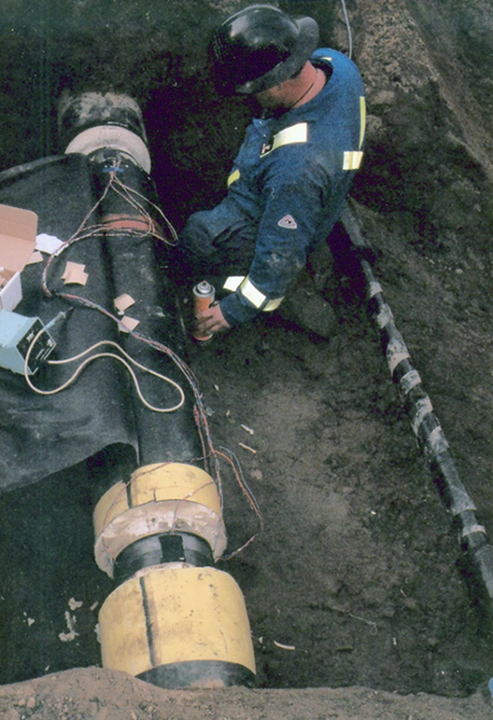
Figure 1 – Field Installation of Strain Gauges
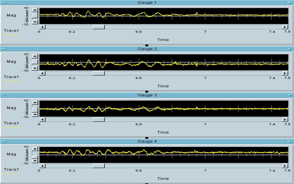
Figure 2 – Dynamic Strain Measurements During Blasting Near Pipeline
Figure 3 shows a strain gauge installation for long term monitoring of a pipeline on an identified unstable slope. The data is continually monitored for any unusual increases in strain readings and can trigger a remote alarm in such an event. Otherwise, the data is collected on-site and transmitted to an office for periodic analysis and review. The data can also be posted onto a website (Figure 4) where the client can examine the gauge results themselves and be assured of the integrity at this location.
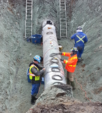
Figure 3 – Strain Gauge Installation on an Existing Pipeline
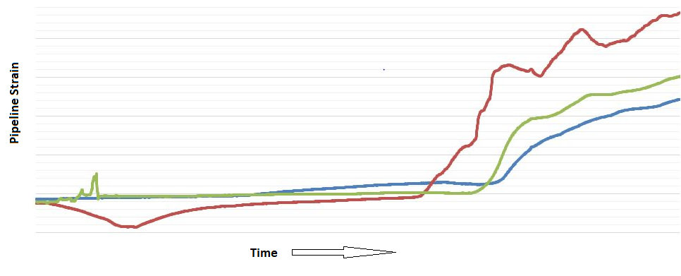
Figure 4 – Example of Increasing Strains during Pipeline Monitoring
For more information about Stress Engineering, please visit: www.stress.com
Share This:


COMMENTARY: Taxes and Regulations Will Increase the Cost of Producing New Energy In Alberta, Making it Less Competitive Than the US – Jack Mintz