CDN NEWS |
  US NEWS


A Magnetic Level Gage may be an excellent addition to the drum level instrumentation on your Power Boiler application. However, in order to properly apply a Magnetic Level Gage on a Power Boiler, you must first understand the specific minimum requirements for water level instrumentation in the ASME Boiler and Pressure Vessel Code. A functional water gage glass is required on all boilers, and it must be in service at all times on applications operating up to 400 PSIG (3MPa). For boilers operated at greater pressures, the Code permits the minimum use of two remote (indirect reading) level indicators on continuous display for the operator combined with a water gage glass. The use of a magnetic type level indicator has a Code limit of 900 PSI (6 MPa). Furthermore, when two remote indicators are in service, the gage glass may be isolated, but must be kept in good working condition. Gage glasses are often used to confirm the actual water level in the drum and for comparison with other instruments, especially at start-up.
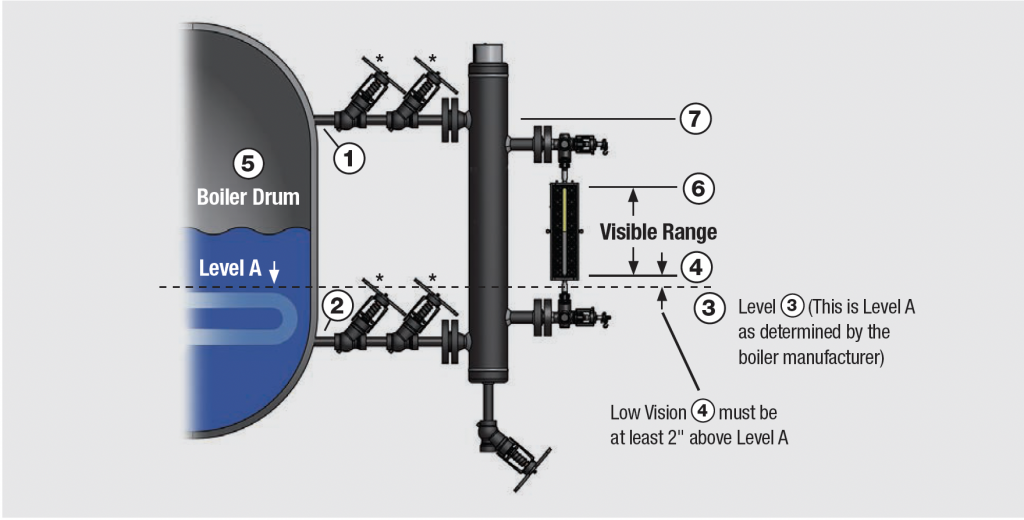
Figure 1: Illustration to establish the proper limits for a Gage Glass
In most modern boiler installations, the operator is located in the control area, in which the gage glass is not within their line of site. To address this situation, the Code requires two independent level indicators that are maintained on continuous display for the operator. Therefore, the Code requirement for two remote indicators provides this critical level information to the operator with validation and confidence. In addition, we recommend using multiple technologies for remote indicators to prevent the risk of common mode failure between systems. The most common technologies of remote water level indication instruments used on Section 1 Power Boilers are those listed below:
- Conductivity probe
- Differential Pressure
- Guided Wave Radar
- Magnetic Level Sensing
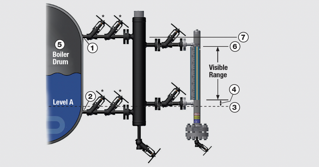
Figure 2: Illustration to establish the proper limits for a Magnetic Level Gage
Magnetic Level Gages are comprised of a stainless-steel chamber with an internal float containing a magnet that causes the externally mounted indicator to respond to changes with the water level in the boiler (See Figure 3). Since the operator is not able to physically see the water as compared to a gage glass, this device is defined as a remote (indirect) level indicator, even though it is locally mounted near the drum. This instrument may be equipped with a transmitter to detect, transmit, and display the level information for the operator in the control area. Any water level sensing device that is externally mounted and relies on conductivity, signal detection & transmission, or magnetic sensing technology is considered to be a remote (indirect) type level indicator. A gage glass is the only type of direct reading level indicator.
- LOW SIDE OUTSIDE DIAMETER OF STEAM CONNECTION OUTLET ON THE DRUM
- UPPER SIDE OUTSIDE DIAMETER OF WATER CONNECTION OUTLET ON THE DRUM
- DANGER POINT, AS DETERMINED BY THE BOILER MANUFACTURER
- LEVEL 2” ABOVE THE DANGER POINT (LOWEST PERMISSIBLE INDICATION LEVEL IN GAGE GLASS OR MAGNETIC LEVEL GAGE)
- DRUM
- UPPER END GAGE GLASS OR INDICATION SCALE ON MAGNETIC LEVEL GAGE
- EXTEND POSITION OF ITEM 1
Successful installations require attention to detail. When specifying and installing a Magnetic Level gage on a Power Boiler application, the ASME Boiler Code requirements are very specific with respect to the position limits of the indication scale relative to the vessel connections. The indication range must meet the same requirements as a gage glass (see Figures 1 & 2). These ASME Section 1 Code requirements are significantly different when compared to the vast majority of Magnetic Level Gages installed on applications other than Power Boilers.
The following Code rules must be met to apply a Magnetic Level Gage:
- The maximum operating pressure is 900 PSIG (6 MPa). This eliminates the concern for deviations with level accuracy on frequent cycling applications at higher pressure service.
- The indication scale limitations are between 2 inches above the danger point, as determined by the boiler manufacturer and the low side of the outside diameter of the steam connection exiting the drum, as identified by locations 1 & 4 in Figures 1 & 2.
- The attachment of any external switches or transmitters to a Magnetic Level Gage for control functions is prohibited.
- The use of a Magnetic Level Gage does not replace the Code required gage glass.
- A Magnetic Level Gage may NOT be used to function as a water column. Other accessories such as a gage glass are prohibited from being attached.
- Magnetic Level Gages must be installed with isolation and drain valves.
- Refer to Subsections PG-12 and PG-60 in Section 1 of the Code for additional details.
To maximize accurate and dependable service life, periodic (annual) float inspections are recommended in order to remove any potential debris that may collect on it. This reasonable maintenance inspection along with periodic blowdowns of the sensing lines will ensure continued and reliable indication. The quality of the boiler water in an application will guide the user with the frequency of inspection. Applications with quality water treatment will require less maintenance.
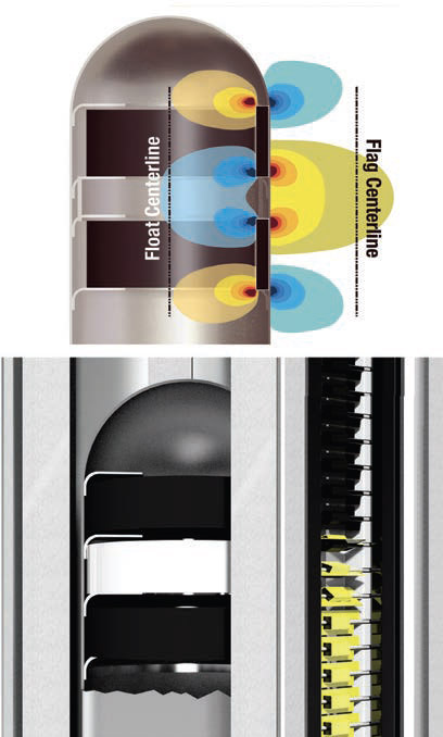
Figure 3: The Magnetic attraction between the float (with internal magnet) in a chamber and an externally mounted indicator
In summary, a Magnetic Level Gage can be a useful instrument to supplement the Code required gage glass for local level indication and a transmitter may be attached to provide an additional signal in the control room, only for remote indication. However, it must be installed according to the Code. It may be helpful to consult with your local trusted product provider such as Westech Industrial Ltd, insurance carrier or local inspector for your plant to confirm the requirements for drum level instrumentation in your specific location.
More Information
For more information on Westech Industrial’s Jerguson Level Gages please visit our website at https://bit.ly/3IDgKaG or call one of our technical representatives at 1-800-912-9262.
Share This: