CDN NEWS |
  US NEWS


In the energy industry, fire and gas detection systems are a critical layer of protection. Yet for decades, the placement of detectors has often relied on a mix of experience, rules of thumb, and conservative assumptions. While this approach has worked, it has also led to inconsistencies—sometimes resulting in overdesigned systems, and in other cases, gaps in coverage.
Today, advances in fire and gas mapping software are shifting this process from subjective judgment to data-driven engineering. One of the most significant developments in this space is the use of plume-based fire modelling, which is redefining how detector coverage is evaluated—particularly in complex facilities.
The Challenge with Traditional Fire & Gas Mapping
Modern facilities are increasingly modeled in 3D environments early in the design phase. These models evolve over time—from simple representations of major equipment to highly detailed layouts that include piping, instruments, tubing, and structural elements.
As these models become more detailed, a key challenge emerges: obstruction. This effect becomes clearer when looking at how a traditional point source model interprets the detector’s field of view from different perspectives, as shown in Figure 1.
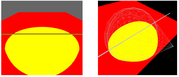
Figure 1: Left: The detector field of view appears largely unobstructed. Right: The rotated view shows how the point source model predicts an obstructed region behind piping, creating a perceived coverage gap.
Traditional fire and gas mapping tools often rely on a point source fire model, where a fire is assumed to exist at a single point in space. While this approach is intentionally conservative, it introduces a significant limitation—especially in detailed 3D environments.
Small obstructions such as piping or conduit can artificially block the line of sight between a detector and a modeled fire.
The result is predicted “blind spots” that may not exist in reality. These gaps can drive designs toward higher detector counts in order to meet coverage targets, increasing both capital and maintenance costs.
Why Fire Is Not a Point
In reality, fires are not infinitely small points—they have volume.
Even a relatively small hydrocarbon fire radiates heat across a measurable surface area. When viewed from a detector, only a portion of that surface may be obstructed by nearby equipment. The rest remains visible, often providing sufficient radiant energy for detection.
The traditional point source model does not account for this. It assumes that if any obstruction exists between the detector and the fire’s central point, detection may fail—leading to overly conservative results.
Introducing Plume-Based Fire Modelling
To address this limitation, newer fire and gas mapping approaches—such as the patented plume model used in Effigy® software—treat fire as a three-dimensional volume rather than a single point.
In this method, the fire is represented as a defined plume with height and width.
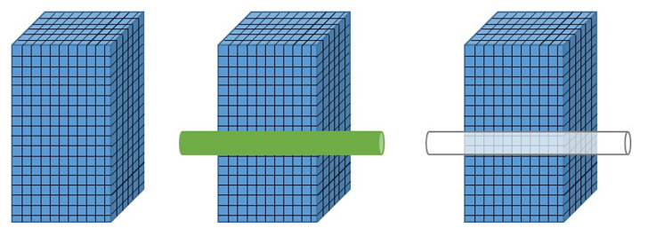
Figure 2: Plume-based modelling evaluates fire as a volumetric source. Even when partially obstructed, a portion of the fire remains visible to the detector, allowing for more realistic detection analysis.
Thermal radiation is distributed across the entire surface of that plume, and each portion is evaluated independently to determine visibility from the detector.
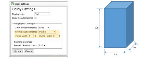
Figure 3: Plume-based models define fire geometry using user-specified dimensions, enabling realistic simulation of fire size and radiative output.
Rather than asking, “Can the detector see a single point?”, the model asks:
“How much of the fire’s radiating surface is visible—and is it enough to trigger detection?”
This shift in approach has a meaningful impact.
Accounting for Real-World Obstructions
In a plume-based model, small obstructions—like a 3-inch pipe—may block only a fraction of the fire’s surface. While that portion is excluded from detection calculations, the remaining visible surface often still provides sufficient radiation for the detector to alarm.
In practical terms, areas that appear “uncovered” in point source models may actually be adequately protected when fire volume is considered.
The Impact on Design and Cost
When applied to detailed 3D models, plume-based fire modelling can significantly improve the accuracy of coverage predictions.
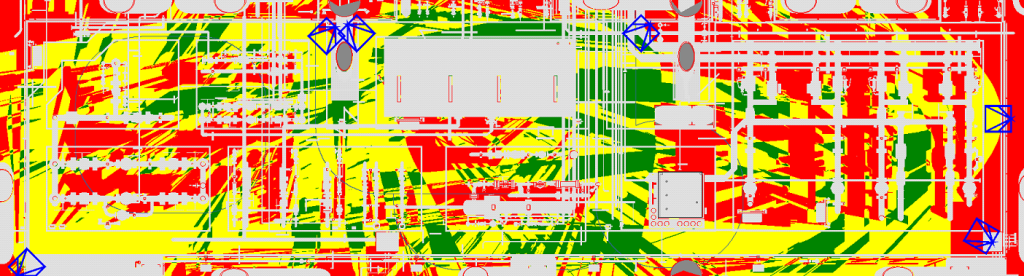
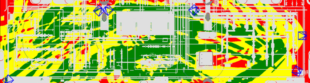
Figure 4: Comparison of detector coverage using traditional point source modeling (top) and plume-based modeling (bottom). Plume modeling provides a more realistic representation of coverage in complex environments.
This has two key implications:
1. More Realistic Coverage Mapping
Facilities with dense piping and equipment no longer appear artificially under-protected. Coverage maps better reflect real-world conditions, reducing uncertainty in the design.
2. Optimized Detector Counts
Because the model avoids overestimating obstruction effects, it often results in fewer detectors required to meet coverage targets—without compromising safety.
For operators and EPCs, this can translate into meaningful cost savings across both installation and long-term maintenance, while still meeting performance requirements.
When Plume Modelling Matters Most
Plume-based modelling becomes particularly valuable in:
- Facilities with highly detailed 3D CAD models
- Areas with dense piping or structural congestion
- Offshore platforms and processing modules
- Brownfield upgrades where obstructions are unavoidable
- Projects where detector count and placement significantly impact cost
In simpler models—where minor obstructions are intentionally excluded—traditional point source methods may still be appropriate. The key is understanding when each approach applies.
Moving Toward More Defensible Designs
As regulatory expectations and safety standards continue to evolve, the ability to demonstrate a defensible, engineered approach to detector placement is becoming increasingly important.
Plume-based fire modelling represents a step forward in that direction. By aligning modelling assumptions more closely with physical reality, it helps bridge the gap between conservative design and practical implementation.
How Westech Supports Fire & Gas Mapping Projects
Implementing fire and gas mapping software is not just about selecting a tool—it’s about applying it correctly.
Westech Industrial works with clients across the energy sector to support fire and gas detection projects from early design through to implementation. This includes:
- Evaluating facility conditions and detection requirements
- Supporting the application of fire and gas mapping software
- Assisting with interpretation of coverage results
- Recommending appropriate detection technologies
- Integrating solutions into broader safety systems
Whether working on new builds or retrofits, the goal is the same: to help ensure detection systems are both effective and efficient—without unnecessary complexity or cost.
Final Thoughts
Fire and gas detection has always been a critical component of industrial safety. What’s changing is how those systems are designed.
Moving from point-based assumptions to plume-based modelling is more than a software upgrade—it’s a shift toward more accurate, defensible, and cost-effective system design.
For facilities with complex layouts, that shift can make a measurable difference.
Looking to evaluate your fire and gas detection coverage? Contact Westech Industrial to discuss your application. Call us today at 1-800-912-9262 or email us at [email protected] or visit our website to learn more about our Kenexis Effigy Software.
Share This: