CDN NEWS |
  US NEWS


![]()
There has been a significant evolution in power semiconductor devices from small, low power devices to very high capacity devices. As a result, multi-megawatt range adjustable speed drive (ASD) systems are increasingly being used not only in the global cement industry but others such as oil & gas, mining, water/wastewater, and power generation. In a modern cement plant, Medium Voltage (MV) ASDs are used on ID fans, kilns, separators, finish mill, ball/sag mills, conveyors, & pumps. A new generation of regenerative medium voltage adjustable speed drives are being applied that not only deliver motor control but also can inject reactive power back to the connected bus. This topology of drives helps in improving power factor and providing voltage support thereby reducing or eliminating nuisance trips due to power instability, optimize the size of backup generators, release capacity tied up in lagging loads thereby enabling plant expansion.

Utility Plant Power
Typical Industrial loads such as shown in the one-line below consist of motors for plant processes, special equipment unique to the facility, and other loads such as plant lighting and HVAC. In AC systems, the current that flows is divided into two components, real power measured in kiloWatts (kW) and reactive power measured in kilovars (kVARs). Both types of power draw current (amperes) from power delivery equipment such as transformers, cable, and switchgear. Current flow results in voltage drop, heating and wasted energy.

Power Factor is Important!
kilowatts and kVARs
What is a kilowatt? kW is the accepted measure of the real energy consumed by any process. It is the product of volts and the part of the total amps flowing that does real work, divided by 1000. This current is called “real” current, and flows in phase with the voltage. This includes the “work” that produces heat in the cables and power delivery gear.
Describing “What is a kVAR?” is a little more difficult. A kVAR is the accepted measure of reactive power, equal to the product of the volts and the part of the current that is “reactive” divided by 1000. Reactive current is the current that flows out of phase with the supply voltage. Reactive current supplying motors lags in time behind the voltage and the real current, as in A below. Reactive current that supplies capacitors leads in time ahead of the voltage and the real current, as in B below. Lagging reactive current magnetizes motors and transformers.
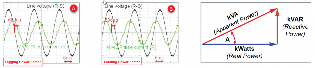
The real power (kW) and the reactive power (kVAR) are related like the legs of a right triangle as in the figure at the above right. Each of the sides is shown as an arrow, called vectors. Since they are at right angles, they cannot simply be added together. The longer vector (kVA) represents the total current (amperes) and the load on the system. The ratio [kW / kVA] of real power (kW) to apparent Power (kVA) is called the power factor (pf). The angle shown as A is the power factor angle. If all kVAR were eliminated, the apparent power (kVA) and real power (kW) would be equal and the power factor would be unit or 1.00.
So Why is Power Factor Important?
Wasted system capacity is one key reason. Poor power factor requires larger transformers, heavier transmission lines, bigger switching equipment. It is becoming more and more common for utility companies to charge industrial users both for energy (kW) and reactive power (kVAR) to cover their real costs. Using the mug of beer as an example – the beer is the kW, the kVAR is the foam. For the same mug, more beer, less foam, more kW, fewer kVAR would be better!

kVAR Demand Sources
Which loads in a user’s plant increase reactive power demand, increase utility billing, and consume system capacity? The largest consumers of reactive power are usually motors. Induction motors commonly have a power factor of 0.85 (sometimes expressed as 85%). If a moderately-sized plant has 3000 kW of motor load at this typical 0.85 power factor, the plant and utility kVAR demand would be 832 kVAR, and the total demand would be 3529 kVA, drawing 17% more current than required for the work to be performed.
How do users improve poor power factor?
The general approach to reduce reactive power demand is to provide reactive current to the system in the opposite (leading) direction to cancel the effect of the motors’ lagging power factor. When the lagging and leading kVARs are equal and opposite, the real power (kW) is all that the system must deliver. The figure at the right shows this, with a source of leading kVARs cancelling the bad effect of the lagging kVARs.

Some specific traditional methods
Some common methods to reduce reactive demand include:
- Connecting capacitors – these must include MV contactors or breakers to connect and disconnect them to match system demand. Also, if VFDs are on the same power bus, reactors must be included to tune the capacitors so that harmful resonant over-voltages do not appear. At a typical cost for tuned, switched capacitor banks of $55 per kVAR (4160 volt) the deficit of 832 kVAR in the example above would require $55 x 832 = $45,760.
- Power motors with Voltage Source (Diode Fed) VFDs – such VFDs present a 0.95 power lagging factor to the power system. No compensation is provided to correct other user system loads.
- Power the motors with an active converter VFD with kVAR reactive power control – such VFDs can hold their own power factor to unity – demanding no reactive power from the system. If added current capacity is available, these drives can export reactive power to compensate for other user loads at between $12 and $25 per kVAR.
Let’s focus on the TMdrive-MVe2’s Exceptional by Design™ feature: Built-in Reactive Power Control
All Variable Frequency Drives (VFDs) provide motor speed control (with potential energy savings and improved process control), and some degree of motor protection. Voltage-source VFDs (typically with diode rectifiers and capacitor DC link) isolate the poor power factor of their connected motors from the utility. For example, a motor with a power factor of .82 lagging would have its power needs met by the output of the VFD, while the input reflects a much improved power factor of (typical) 0.95 lagging.
TMEIC’s TMdrive-MVe2 VFD input converter is configured with a unique “Active Front End” that uses active switches in place of diode rectifiers. This allows the converter of the VFD to hold unity power factor at its input terminals. But the TMdrive-MVe2 and control goes beyond that and can actually correct the system Power Factor demands of other nearby utility loads without adding capacitors.
High Power Factor = Possible Savings
TMEIC TMdrive-MVe2 Reactive Power Control
Reactive Power (VAR) control (3) is inherent in the TMdrive-MVe2 VFD. Some capacity is available in all frames to provide some export of kVAR to the user’s system. Plus, by selecting a larger frame than needed to supply the connected motor, additional kVAR export capacity can be made available.
How does it work?
The TMEIC TMVe2 System Diagram below shows the power and currents flowing in and out of the drive, motor and user power system.
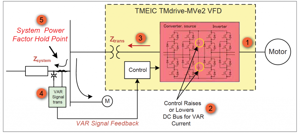
- VFD Converter DC Bus Volts (2) is raised to push leading reactive power (3) into the transformer & system. When current flows out to the utility by raising DC capacitor bus volts, it is effectively reactive current.
- Resulting Current leads voltage if the DC bus is greater than the system nominal, and lags voltage if the DC bus is less than system nominal.
- Transducer (4) creates feedback signal to regulate VARS and power factor (5).
The TMdrive-MVe2 VFD itself with its connected motor always runs at unity power factor, with all of its utility current doing useful work. However, any excess MVe2 VFD converter capacity may be applied to kVAR compensation to free system capacity, or possibly reduce the plant’s utility power factor billing.
Performance and Economic Comparisons
Switched power-factor correction capacitor systems apply their kVAR correction in relatively large, system – shocking steps. By contrast, the TMdrive-MVe2 kVAR compensation is smooth and continuous. Because prices for incremental TM-MVe2 KVA capacity to provide kVAR compensation are 25% to 50% of capacitor system price levels, this looks like a great way to go!
Evaluating the TMdrive-MVe2 Reactive Power Control at your facility
The first step will be to create or update a plant system one-line. Be sure to add the present loads. Include all motors with their nameplate power factors. Identify ratings, application, quantity, and connection points of any TMdrive MVe2 drives. Gather utility rate tables to determine power factor costs.
From here, evaluate the operating condition cases. Evaluate the TMdrive MVe2 potential contribution to reactive power to evaluate any potential savings. Westech Industrial has a simple spreadsheet evaluation tool created by TMEIC to help with this. The tool allows clear determination of kVAR contribution with right-sized VFDs [sufficient to carry the motor loads attached] or with upsized VFDs with extra capacity for reactive power compensation.
Your savings may come from released system capacity by allowing your present power distribution equipment to carry more plant load with no additional investment. Or, there may be potentially reduced utility billing based on their rate structure in place for your facility.
Built-In Reliability and Performance
When something is better in many areas it is exceptional! TMEIC includes all the aspects of equipment quality and user benefits in the design. Every product, every service, every manufacturing step, including quality control and product support – all areas work together so well, they are truly exceptional.
What makes the TMdrive-MVe2 Exceptional by Design™?
- Very High Reliability – 15 year MTBF
- Simple design
- Clean power to the utility system & motor
- Built-in Reactive Power Control
- Minimal spare parts
- Long-life film capacitors
- 24 hour x 365 day live support in North America
- Remote Connectivity troubleshooting built-in
More Information
For more information on Westech Industrial’s TMEIC TMDrive MVe2 please visit our website at https://bit.ly/313LxbP or call and speak to one of our technical representatives at 1-800-912-9262.
Share This: