CDN NEWS |
  US NEWS


Combustion processes are an integral operation in refineries, petrochemical, fertilizer, and power plants across the globe. Rising fuel costs and increasing competition are driving plants to adopt new techniques for measuring combustible gases with the goal of optimizing their combustion processes. Leading the pack is tunable diode laser (TDL) technology. A new generation of TDLs not only offers exceptional fuel costs savings, but eliminates the need for process side purge gas.
Introduction
Refineries, petrochemical, fertilizer and power plants worldwide have large numbers of combustion processes in operation, from process heaters and fired heaters to package boilers and large steam turbines. Whenever a process fluid needs to be heated as part of a chemical reaction, or there is a requirement for steam generation, there will be a combustion process at its heart.
This article presents a review of the general anatomy of a typical combustion process; describing each zone and its function, before discussing some of the challenges of combustion measurement and how modern TDL analyzers such as METTLER TOLEDO’s GPro 500 and its range of process adaptions offer many advantages over typical combustion analysis technologies. Finally, a selection of specific combustion applications will be described, highlighting the typical process conditions. These applications are ideal candidates for superior TDL combustion measurement.
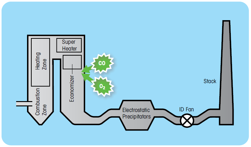
Figure 1: Diagram of a generic combustion process
Anatomy of a general combustion process
In the above diagram we have seven general zones that follow a linear procession from the combustion zone to the emission stack.
- The combustion zone is where the burners are located and as the name suggests, this is where the highest temperatures are to be found. For some applications temperatures can reach 1,200 –1,500 °C (2,191 –2,732 °F). Depending on the capacity, there may be multiple burners.
- The heating zone or radiant section (sometimes called the firebox) is the region directly above the burners. Temperatures here can be typically 700 –1,200 °C (1,292 –2,191 °F). In the case of fired heaters, in this section there will be radiant tubes where the compound to be heated will be exposed to the highest temperatures.
- The super heater is a device that superheats steam and will be typically found in steam reformers. Its main purpose is to increase the temperature of saturated steam without raising its pressure.
- Economizers are used to recover some of this heat from the combustion. Stack economizers are utilized to increase efficiency when large amounts of makeup water are used (e.g. when not all condensate is returned to the boiler or large amounts of steam is consumed in the process, so there is no condensate to return) or there is a simultaneous need for large quantities of hot water for some other use. Savings potential is based on the existing stack temperature, the volume of make – up water needed, and the hours of operation. Economizers are available in a wide range of sizes, from small coil-like units to very large waste heat recovery boilers.
- Electrostatic precipitators remove particles from the gas stream using electrostatically charged plates. The operation of this device is covered in more detailed in our white paper covering non-combustion CO applications for the GPro 500 TDL. To recap, fast response CO measurement is often a requirement to ensure that flammable gases do not reach the electrostatic plates, and therefore reduce explosion risk.
- The ID fan is used to ensure there is a forced velocity of cleaned gas fed to the stack to ensure good dispersion. 7. Finally, the stack ensures that the cleaned flue gas is dis – charged well above ground level for atmospheric dispersion.
- Finally, the stack ensures that the cleaned flue gas is discharged well above ground level for atmospheric dispersion.
Understanding the combustion process
The whole purpose of measuring combustion gases is to optimize the efficiency of the combustion process and therefore reduce fuel costs and reduce wear to plant and equipment. To understand efficient operation, the process of combustion should first be understood.
Stable combustion conditions require the right amounts of fuel and oxygen. The combustion products are heat energy, carbon dioxide, water vapor, nitrogen, and other gases (excluding oxy – gen). In theory, there is a specific amount of oxygen needed to completely burn a given amount of fuel.
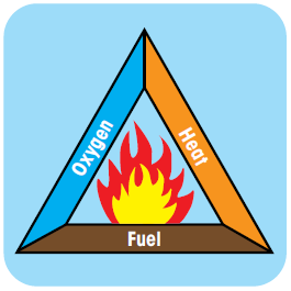
The famous combustion triangle tells us that for combustion to occur we need three things:
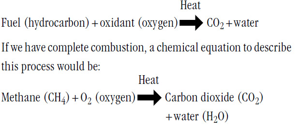
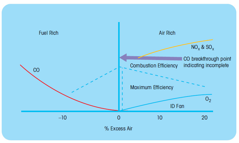
Figure 2: Effect on combustion efficiency caused by changes in excess air levels
In practice, combustion conditions are never perfect. Therefore, more air than necessarily has to be supplied to burn all fuel entirely. To determine the amount of excess air which will be required for any particular combustion system, we have to start with the stoichiometric air-fuel ratio, known as the perfect or ideal fuel ratio, or the stoichiometric combustion. During stoichiometric combustion there is a chemically correct mixing proportion between the air and the fuel. During such a process no fuel or air will be left over. For total combustion the stoichiometric equation would be:
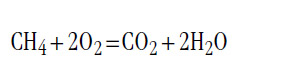
Process heating equipment almost never runs in stoichiometric balance. Even so-called “on-ratio” combustion, used in boilers and high temperature process furnaces, incorporates a modest amount of excess air – 10 to 20% more than needed to burn the fuel completely.
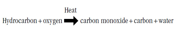
If insufficient air is supplied to the burner, unburned fuel, soot, smoke, and carbon monoxide are exhausted from the boiler. This results in surface fouling, pollution, lower combustion efficiency, flame instability and a potential for explosions due to excess combustible gas generation.
To avoid these inefficient and unsafe conditions, combustion processes have traditionally operated at a high excess air level. The excess of air also provides protection from insufficient oxygen conditions caused by variations in fuel composition and operating variations in the fuel-air control system.
To increase the efficiency and safety of the process, it is desirable to reduce the amount of excess air, while ensuring that conditions of incomplete combustion and high levels of combustible gases are not reached. This is difficult to achieve and control consistently without good feedback of the current O 2 and CO concentrations post combustion.
This is where the use of highly reliable and accurate O2 measurement combined with a combustible gas analysis can provide the critical real-time and in-phase analysis data required. Whereas, the measurement of oxygen provides a good understanding of the amount of excess air being utilized, the accurate measurement of the combustibles, in the form of CO, provides the fine control signal to indicate when the excess air has been reduced too much and incomplete combustion is occurring. This is because at the point where incomplete combustion begins to occur, there will be a very sudden rise in the level of CO. When this point is reached the operator will open the dampers. This is typically automated on larger process heaters and power generation plant equipment.
Challenges of combustion measurement
– Oxygen and CO measurement (CO trim control)
Again with reference to Figure 2, it can be seen that the ideal control point (maximum efficiency) is just above the level where CO breakthrough begins to occur, as the conditions begin to move into the fuel rich region. This CO breakthrough is very rapid indeed with sharp CO peaks occurring as the oxygen level (excess air) is reduced. It can therefore be appreciated that the addition of a fast responding and accurate CO measurement is essential for precise control of the combustion conditions by in – creasing or decreasing the excess air level to o the furnace. This technique is known as “CO trim control”.
There are therefore two distinct approaches in combustion measurement:
- Combustion monitoring: Only oxygen is measured for combustion monitoring. Therefore, the maximum efficiency point cannot be precisely controlled and is only determined by burn – er design information or modelling, meaning the burner is normally operated with more excess air than necessary, as a safety margin.
- Combustion control: Where CO measurement allows more precise control of the process by monitoring for the CO break – through point to provide adjustment of the excess air to account for changes in fuel composition, loading and atmospheric conditions, etc.
For many modern high efficiency, low NO x burners, the CO levels can rise very quickly indeed, from typically less than 10 ppm(v) to greater than several 100s ppm(v) for just a few thousand ppm(v) change in the O 2 value. This highlights again the need for a fast response CO analysis if CO trim control is to be successful. A slow CO analysis, or one that is “out of phase” with the oxy – gen measurement, will lead to inaccurate trim control and over or under compensation of excess air leading to continuously unstable combustion conditions.
– Typical excess air values and dust loading considerations
Large power plant boilers and process heaters can run with as much as 10 to 20 percent excess air, while some natural gas-fired boilers and low NO x burners may run as low as 5 percent excess air. Pulverized coal-fired boilers typically run with 20 percent excess air with some solid fuel coal-fired plants operating at much greater levels. Typical values of excess air for some common fuels are shown in Table 1.
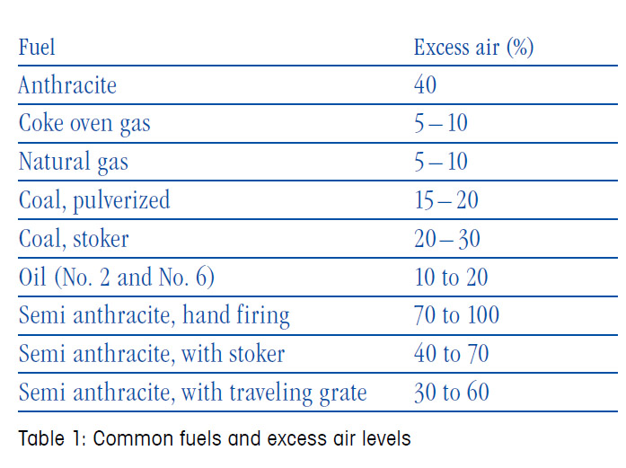
As had been discussed, the goal is always to reduce the level of excess air as far as possible, while maintaining complete combustion. These figures only provide broad guidance and actual values will depend on the design and age of the equipment as well as the type and origin of the fuel used:
Note: From the above table it can be seen that gas or oil-fired combustion processes require considerably less excess air for efficient combustion and will generate much lower particulate concentrations. All combustion applications will have variations in particulates or fly ash loading. Due to the heavy particulate (fly ash) present in the gas stream from some coal-fired installations, special care should be exercised to investigate and understand the concentration and type of particulates that may be present under these circumstances, to ensure that sufficient filtration of the sample is provided.
The economics of combustion control
Example of typical savings on a typical battery of 6 gas-fired heaters:
- Fuel costs for the production of 200 m BTU/hour energy per heater: with unit price of 4 $ per m BTU/hour, the total amount is 7 m $ per heater per year.
- If excess air can be reduced by 1.5 % O2, the estimated savings on fuel will be 1 %, or 70,000 $ per heater/year.
- Considering total costs of ownership (equipment, installation, engineering, and spares for an estimated analyzer lifetime of 5 years) of 75,000 $ for one O2 and one CO analyzer per heater,
- The investment will be cash positive in 13 months, with a total 5-year return on investment of 275,000 $ per heater, or 1,65 m $ for the whole heater battery.
- Additional, collateral benefits are cost savings for significantly lower NOx and CO emissions.
The above example clearly demonstrates the significant economic drivers that focus the desire to optimize efficiency of combustion processes throughout the plant.
Catalytic combustion sensors and their limitations for precise combustion control
The majority of combustion sensors in common use are based on pellistor technology. A pellistor, also known as a catalytic or heated bead sensor, consists of either a single, or more commonly a pair of matched precision resistors onto which two different coatings are applied (see figure 3). The first pellistor bead is coated with a catalyst that creates an exothermic reaction when exposed to combustible gases, principally but not exclusively carbon monoxide. The second bead is covered with an inert (non-reactive) coating and is used as a reference to reduce temperature variations (due mainly to process flow) from generating errors in the measured value. In order to increase the reaction rate on the catalyst, the pellistors are typically heated to about 500 °C (930 °F). The pellistor pair is typically configured into a Wheatstone bridge.
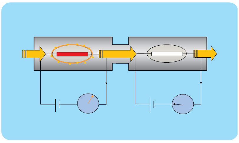
Figure 3: Typical pellistor matched-pair arrangement
These sensors are non-CO specific. As mentioned above, they operate by detecting a temperature change due to combustion occurring on a catalytic surface. This means, however, that all combustible gases will react, and consequently they will report a false CO measurement if other combustible gases are present. In addition, they typically have poor accuracy, sensitivity, and response time, resulting in inaccurate or delayed detection of the CO breakthrough point. As these are catalytic contact sensors, the process gas is in direct contact with the sensor itself and can poison the catalyst, which limits sensor lifetime and affects measurement reliability.
Pellistor limitations
Pellistors are quite crude sensors, providing typical measurement ranges of 0 –2,500 ppm(v) ±125 ppm, and suffer from a number of limitations, including:
- Pellistors not being perfectly matched (balanced), which creates measurement offsets
- Radiative heat losses from each bead being different, again creating imbalance and measurement errors
- Dirt in sample building up on sample pellistor but not on reference, causing sensor drift
- Use of a simple catalyst which is easily poisoned or inhibited and not selective to CO, leading to measurement errors.
Together, these limitations result in, at best, a fairly crude and unreliable CO e (CO equivalent) reading. This is hardly ideal for effective combustion trim control.
Other CO measurement techniques
In the past, nondispersive infrared (NDIR) CO analyzers have sometimes been used for CO combustion measurement applications. While they can offer excellent measurement performance and CO specific determination, most rely on extractive sample handling systems which can result in measurement and maintenance issues, including:
- Slow response due to sample conditioning and transportation times
- O2 and CO signals being out of phase due to differences in sampling times or instrument response, even when the sample is drawn from the same location
- High maintenance requirements for the sample conditioning system
- Blockage of sample transport lines caused by particulate loading
- Failure of heated transport lines
- Fouling of extractive sample cells
- Cost of purchase of suitable extractive analyzers with heated sample cells
- Cost of sampling system and heated lines. The above limitations have largely resulted in the demise of extractive NDIR analysis in the majority of combustion applications
The ideal CO combustion analyzer
To guarantee the maximum integrity for the CO measurement, several things should be considered. These include:
- In situ measurement not requiring a sample handling system
- CO specific measurement versus a non-specific total combustibles measurement.
- Accuracy of the combustibles measurement
- Speed of response
- In-phase measurement
- Reliability
- Sensor lifetime
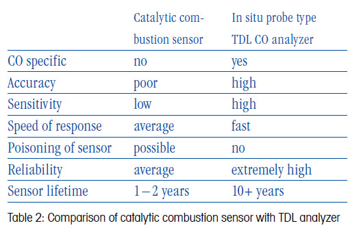
In comparison with the many drawbacks and technical compromises of catalytic sensors and extractive NDIR technology, a modern, in situ, probe-type TDL, such as METTLER TOLEDO’s GPro 500 series, offers considerable measurement, operational, and cost benefits. Table 2 highlights the advantages that a high integrity, CO-specific TDL measurement provides for accurate and reliable combustion control measurement.
One significant challenge for TDL analyzers, particularly for combustion monitoring or control applications, has been the significant consumption of purge gas to protect the analyzer’s optical windows. Even though probe-type TDLs reduce purge gas consumption considerably compared with earlier cross-stack de – signs (and eliminate the need to align the sender and receiver units), this can still be a constraint, particularly for retrofit installations.
This limitation has been overcome by the release of a range of innovative process adaptions designed to augment the already high-performance measurement of the GPro 500 TDL.
Figures 4, 5, and 6 illustrate the design of the GPro 500 and the variety of available process adaptions. These process adaptions offer an interface solution for a wide range of applications, creating a fully flexible measurement solution, and allowing successful installation of TDLs into processes and locations once thought impractical, or even impossible.
In the case of combustion monitoring and control, the most appropriate process adaption is the non-purged (NP) filter probe, either the standard design (Figure 5) or with filter blowback facility (Figure 6). The filter provides protection for the analyzer’s optical surfaces without the need for the traditional process side purge; simplifying installation and reducing long-term operating costs.
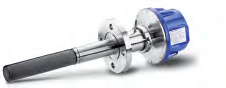
Figure 5 – GPro 500 TDL with non-purged (NP) filter probe

Figure 6: Non-purged (NP) filter probe with blowback
These probes have been designed specifically with combustion processes in mind and provide a reliable “fit and forget” solution.
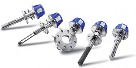
Figure 4: The range of process adaptions available for the GPro 500 TDL series.
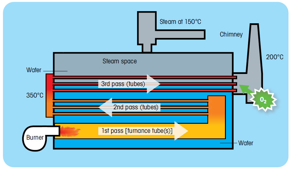
Figure 7: Diagram of typical package boiler
Combustion process systems
1) Package boilers
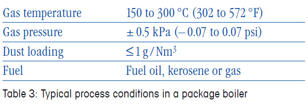
A package boiler refers typically to relatively small scale, pre-designed or “off the shelf” boilers which are available in a large number of types and capacities. Due to their optimized designs, they are very efficient and typically use less fuel and electric power to operate than non-integrated designs. They are therefore commonly used in a large variety of applications in the food, light industrial, pharmaceutical, food, ceramic, and associated industries.
Just as with other combustion process units, a package boiler operates more efficiently when the excess air concentration in the flue gas is reduced while always ensuring that incomplete combustion is avoided. Optimizing air intake for boiler operation requires continuous measurement of the oxygen concentration in the flue gas.
The typical package boiler is a water tube boiler or flue and smoke tube boiler with a capacity of 5 to 20 t/h (average steam generation capacity). The most widely used fuels are heavy oil, light oil, and gas.
2) Process heaters
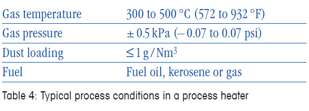
The term “process heater” commonly refers to any process in the plant which directly employs hot combustion gases to raise the temperature of a gas or liquid process stream. Process heaters are, in effect, heat exchangers and are used extensively throughout refineries and petrochemical plants. They are the main consumers of fuel on site and are therefore a major focus for combustion efficiency optimization.
Process heaters consist of multiple coils of tubes inside of which the process fluid passes. Typically, in a refinery this will be a liquid hydrocarbon stream which needs to be heated to a set temperature before entering a refining stage of the plant. The stream is heated by heat exchange with the hot flue gases as these rise through the heater, and also directly by heat from the burners in the radiant section of the heater.
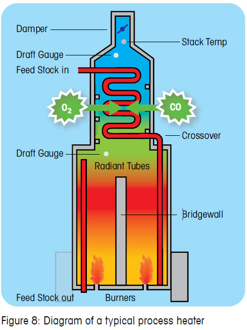
Although there are many types of process heaters and thermal crackers, the general analyzer application requirements are similar for all of them. The typical example shown in Figure 7 is a natural draught unit, fired by arrays of burners using natural gas, sour gas, or waste oil as fuel.
The fuel flow and air supply to the process heater burners are controlled by the rate of process production. The combustion air flow is controlled by adjusting the position of the air damper(s). Without a flue gas analysis of the excess air in the flue, the process operator has to assess the position of the dampers manually, based on experience and/or heater manufacturer estimates, and will therefore take the safest approach, i.e., typically introducing a significantly increased level of excess air to ensure that all fuel is burnt under all load and fuel conditions. This decreases the efficiency of the heater due to flame temperature loss and heat loss to the stack, and increases the risk of NOx production.
Fast analysis of the oxygen concentration in the flue gas allows the excess air levels to be reduced, improving efficiency and safety while at the same time providing an adequate air margin to ensure complete combustion. If this is also combined with a combustibles (CO) analyzer and trim system, this enables the excess air levels to be controlled precisely and offers detection of the onset of incomplete combustion, thus giving the optimal combustion efficiency for every fuel.
Flue gas measurements are specified on a wet basis (i.e., directly in the flue gas) and therefore have long been based on zirconia technology as this eliminates the need for sampling systems and minimizes measurement response times. However, based sensors have a limited life, their catalytic surfaces can be poisoned, and flame out conditions in the heater can present an explosion hazard due to the hot internal surfaces of the sensor (unless expensive flame arrestors are utilized).
On the other hand, probe-type TDLs such as the GPro 500 offer a purely optical measurement technique and are immune to these drawbacks. They provide an extremely long lifetime without raising concerns of sensor damage or safety issues, and represent a more reliable, accurate, and cost-effective solution.
In addition to combustion control analysis there may also be requirements to measure the stack emissions from process heaters and thermal crackers. The analysis required will be governed by local legislation and the fuels being used, but will typically include oxygen, carbon monoxide, and nitrogen oxides.
3) Refinery process-fired heaters
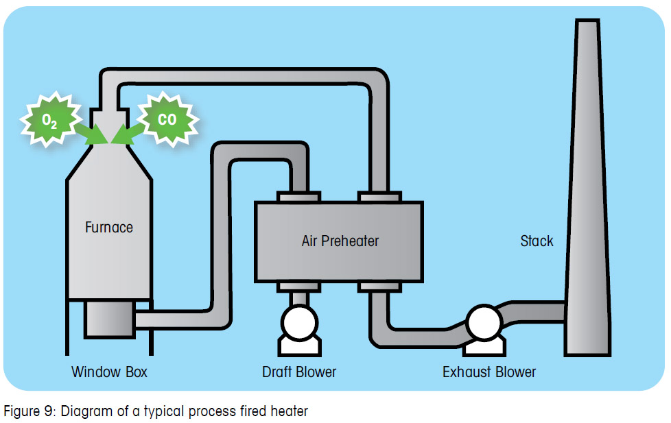
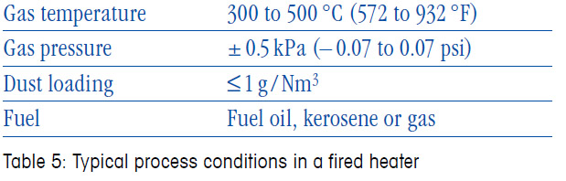
Fired heaters share the same characteristics as process heaters and indeed their names are largely interchangeable. For gas or oil-fired heaters the measurement requirements and process conditions are shown in Table 5. Larger fired heaters may consist of many “cells”, each of which contain multiple burners, and for these, multiple analyzers may be necessary. This approach ensures that an analysis is dedicated to each bank of burners and their burner control system.
The critical performance parameters for both oxygen and combustibles measurement are speed of response (typically ≤ 10 s total for T90 is required), analyzer integrity, and measurement repeatability. In situ TDL analyzers are highly suited for use in fired heaters as they offer fast speed of response (< 2 sec), precision long life measurement, specific CO determination, and are unaffected by catalyst poisons in the gas stream that can damage other sensors.
Power generation boilers are usually large to very large facilities. Single O2 or O2/CO measurement may be utilized on smaller cogeneration plants, but on larger plants multiple measurement points may be configured in the flue. For gas-fired plants the particulate loading will be reasonably low, increasing somewhat on oil-fired units. Typical flue gas temperature after the reheater are in the region of 300 °C and this presents another ideal application for TDL measurement of both O2 and CO.
Again, for this application, TDL technology offers the benefit of fast speed of response, specific CO measurement, immunity to background gases and catalytic inhibitors in the process stream, and superior sensitivity and lifetime, reducing ongoing cost of ownership.
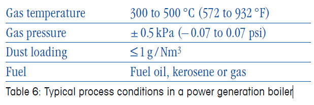
4) Heavy oil or gas-fired power generation boiler
Power generation boilers are usually large to very large facilities. Single O2 or O2/CO measurement may be utilized on smaller cogeneration plants, but on larger plants multiple measurement points may be configured in the flue. For gas-fired plants the particulate loading will be reasonably low, increasing somewhat on oil-fired units. Typical flue gas temperature after the reheater are in the region of 300 °C and this presents another ideal application for TDL measurement of both O2 and CO.
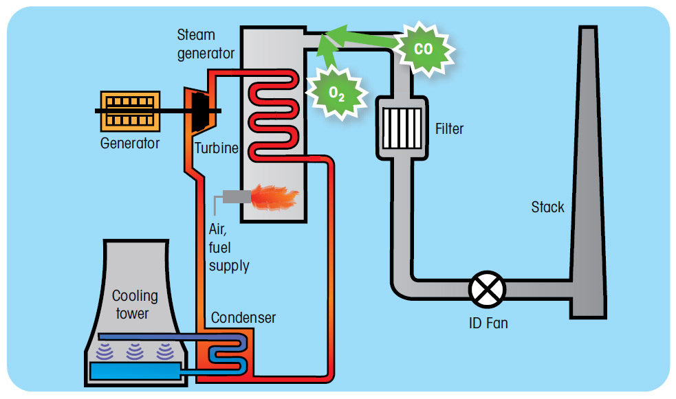
Figure 10: Diagram of typical power generation boiler.
Again, for this application, TDL technology offers the benefit of fast speed of response, specific CO measurement, immunity to background gases and catalytic inhibitors in the process stream, and superior sensitivity and lifetime, reducing ongoing cost of ownership.
Conclusion
Tunable diode laser analyzers are at the forefront of gas analysis and are increasingly the first choice for an ever-growing number of applications which were once the province of extractive gas analyzers. Now they are also challenging zirconium oxide and catalytic technologies throughout a range of combustion applications, where their measurement precision, lower cost of installation and operation, minimal maintenance, fast response times, and reliability has cemented their reputation as the technology of choice.
A new generation of TDLs with innovative process adaptions, takes the core benefits of TDL technology, but overcomes earlier drawbacks of alignment difficulties and the requirement of optical process purge gas, to provide a truly flexible, easy to install, compact, and reliable TDL solution for combustion measurement.
Find out more about Westech Industrial’s Mettler GPRo TDL by visiting our website https://bit.ly/3ExXY3d or call to speak to one of our technical representatives at 1-800-912-9162.
Share This: